6-DOF Robot Arm
A 3D-printed six-axis arm, built at home for $700
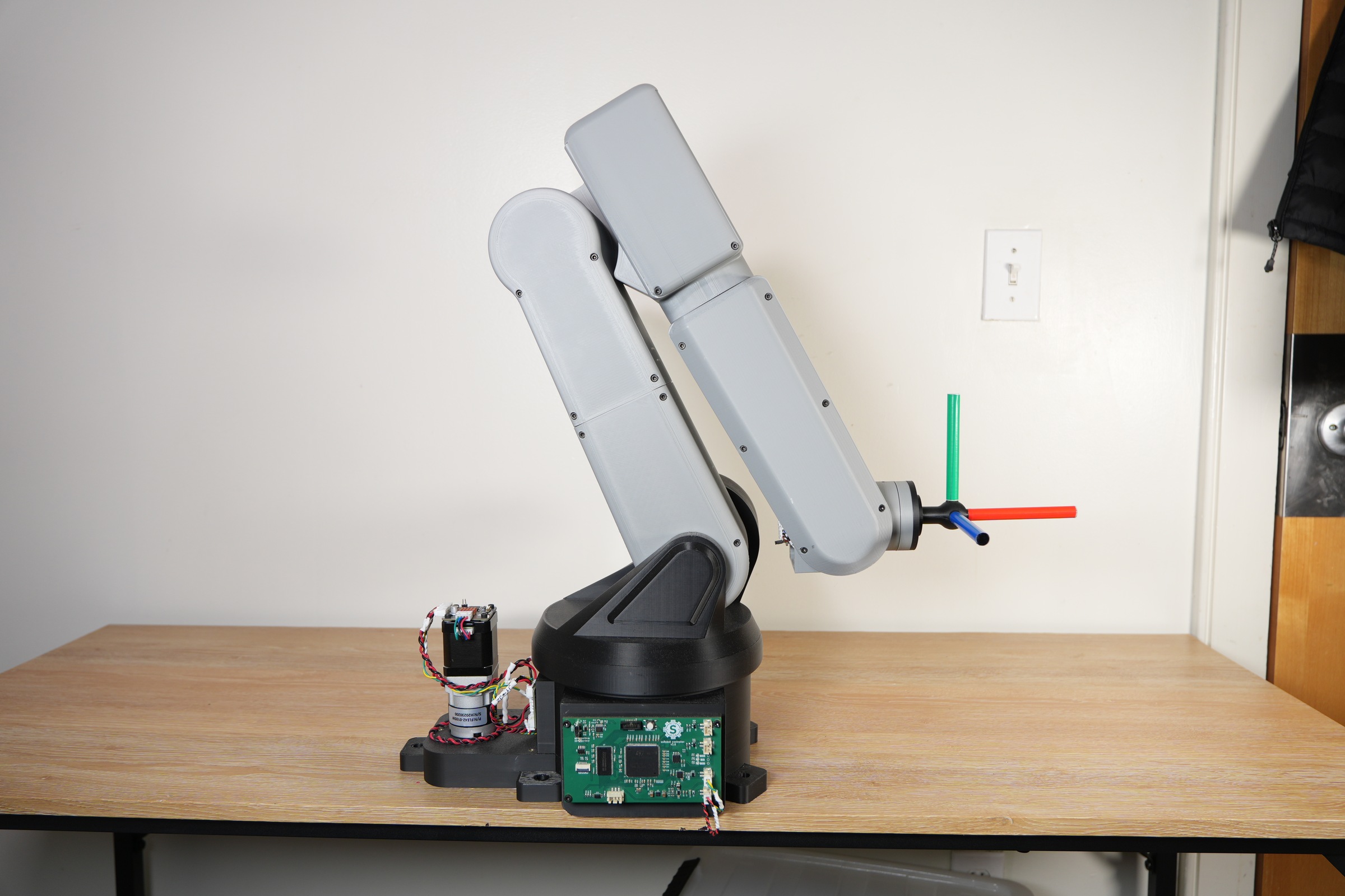
My twin brother Steve and I built a six-axis robot arm at home for about $700. It started in 2023, when I watched a YouTube video of someone's DIY six-axis arm and wanted to see if we could build one ourselves for under $1,000. Commercial arms with this kind of reach cost $10k to $50k, and the cheap hobby arms I found couldn't move in a straight, repeatable line, so we decided to build our own.
I designed the mechanical side in Fusion 360 and handled sourcing and fabrication. Steve designed the electronics and firmware. This page is mostly the story of the mechanical problems we hit and how we fixed them, plus a high-level look at how the arm figures out where to go and how to get there.
Goals
- Cost: under $1,000
- Reach: 600 mm (23.6 in)
- Payload: 1 kg (2.2 lb)
- Six degrees of freedom, with a spherical wrist
- Coordinated Cartesian motion: the tool should follow a straight line in space, repeatably, not just wave its joints around
Design Evolution
Actuators
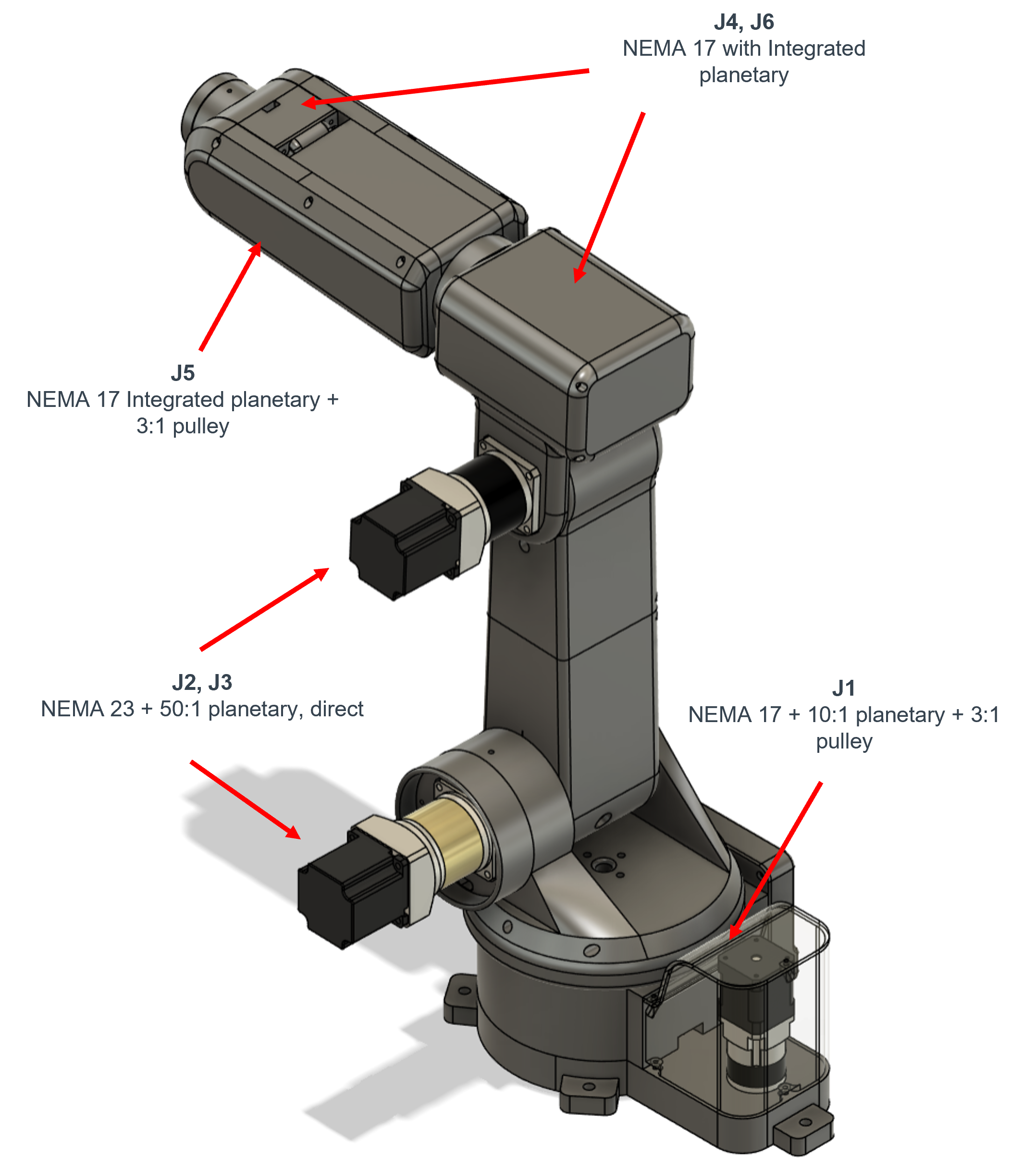
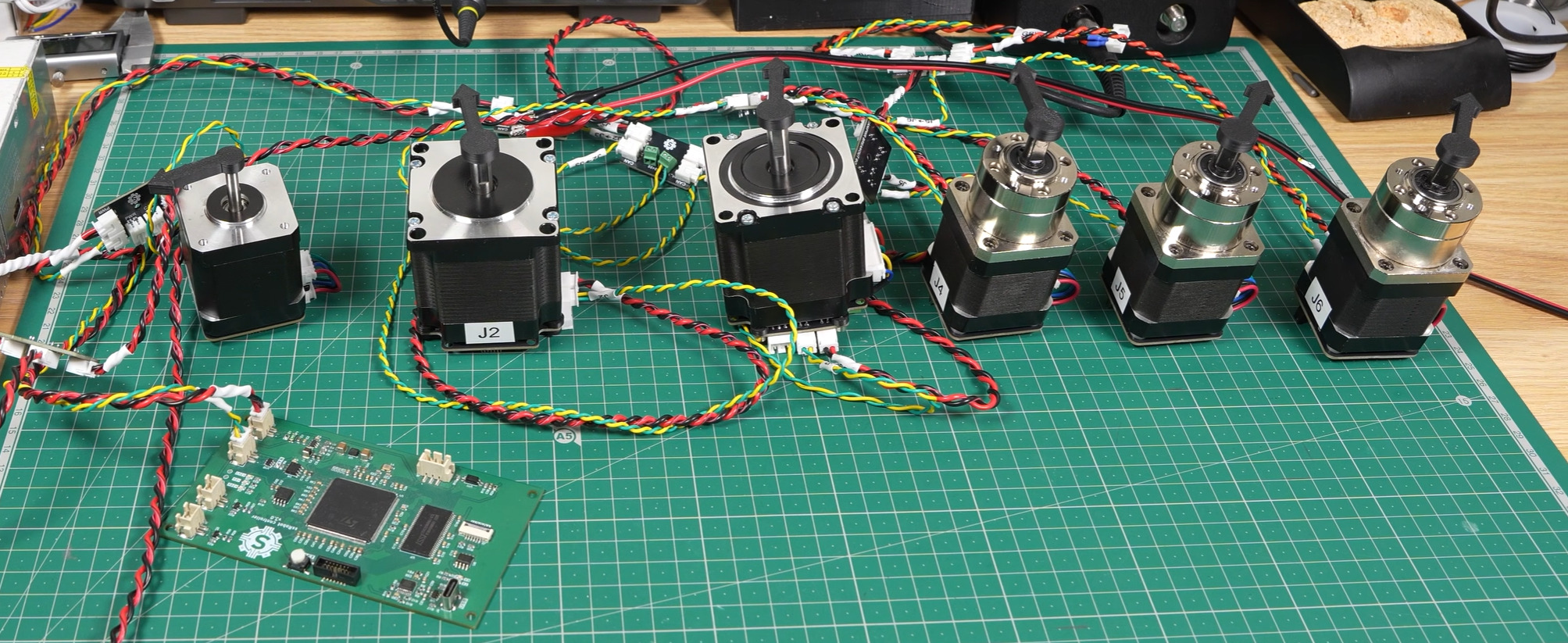
Every joint uses a stepper motor with a planetary gearbox. I bought everything from AliExpress and Amazon, picking the cheapest parts that looked reliable. Steppers made sense for the budget because they're really cheap, they hold position without any feedback, and the drivers are easy to find.
| Joint | Motor | Reduction |
|---|---|---|
| J1 (base) | NEMA 17 | 10:1 planetary + 3:1 pulley = 30:1 |
| J2 (shoulder) | NEMA 23 | 50:1 planetary, direct |
| J3 (elbow) | NEMA 23 | 50:1 planetary, direct (belt-driven in V1) |
| J4 | integrated planetary | 5.18:1, direct |
| J5 | integrated planetary | 5.18:1 + 3:1 pulley, about 15.5:1 |
| J6 | integrated planetary | 5.18:1, direct |
J2 and J3 get the biggest motors because they carry most of the arm. The wrist joints (J4 to J6) only move the tool, so small motors with a light reduction are enough.
Joint 3 redesign
In the first version, J3 (the elbow) was driven by a timing belt that ran the full length of the upper arm. It slipped. The arm couldn't even hold itself up, let alone a payload.
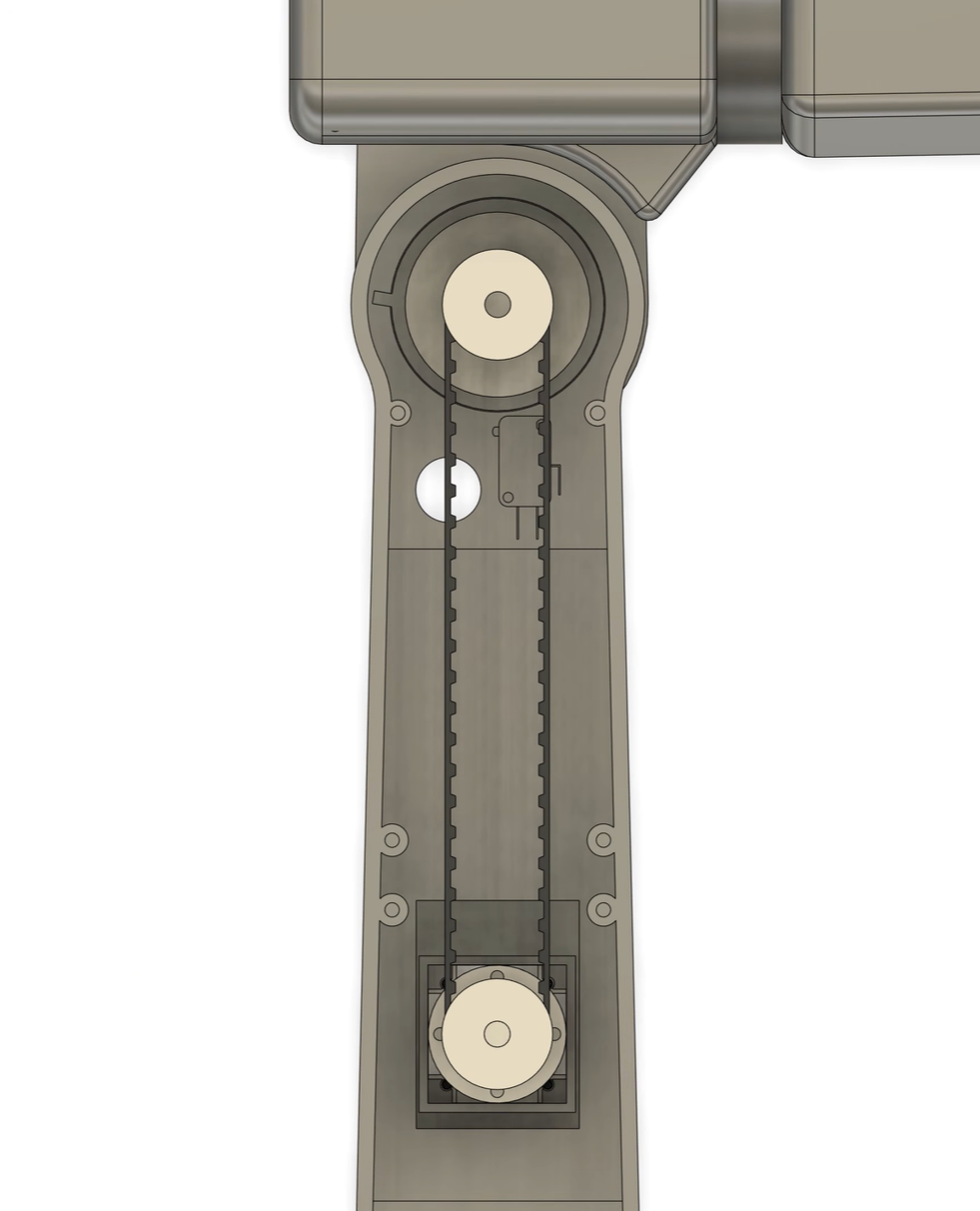
My first guess was that the motor was too weak. So I redesigned the joint to take a bigger stepper, going from a NEMA 17 to a NEMA 23. That didn't fix it. We tensioned the belt harder and harder, and the joint was still jittery and slow.
The real problem was the belt itself. The L-series timing belts we used are meant for metal machines, and they need a lot of tension to work. We were hanging all of that tension on a 3D-printed shaft. Eventually, the shaft that connected the pulley to the elbow just gave out.
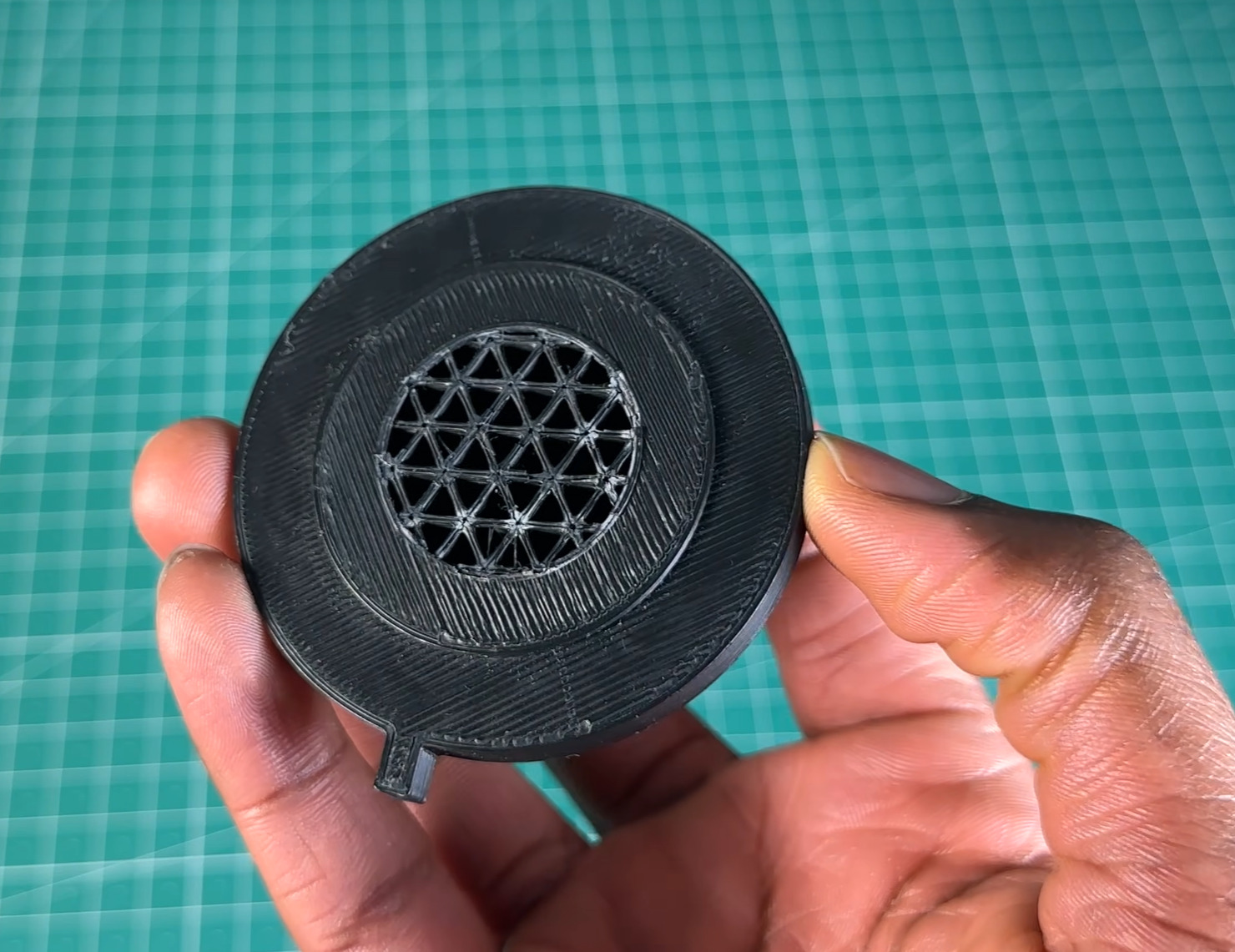
Looking at that fracture surface is when it clicked for me. More tension was never going to work, because the part couldn't take it.
We got rid of the belt on J3 entirely and mounted the motor directly at the joint. That adds weight further out on the arm, but J2's 50:1 reduction had enough margin to absorb it. Mounting the motor at the joint also killed the backlash and jitter that the belt had been adding, so we got a better joint out of the failure.
Wiring
With J3 fixed, the arm worked, but it still had three problems:
- The base wobbled under load.
- Way too many wires ran through the arm.
- Joints would occasionally skip, and since the steppers were open loop, nothing noticed.
The wiring was the worst of the three. Every motor had 6 wires (4 for signals: step, direction, and two limit switches, plus 2 for power), and every one of them ran back to the controller or the power supply. That meant 24 wires coming out of the controller PCB and 14 coming out of the power supply (2 for each motor, plus 2 for the controller). All of it had to snake through a moving arm, where it gets flexed every time a joint turns. That's an assembly nightmare, the wires fatigue, and long signal lines pick up noise.
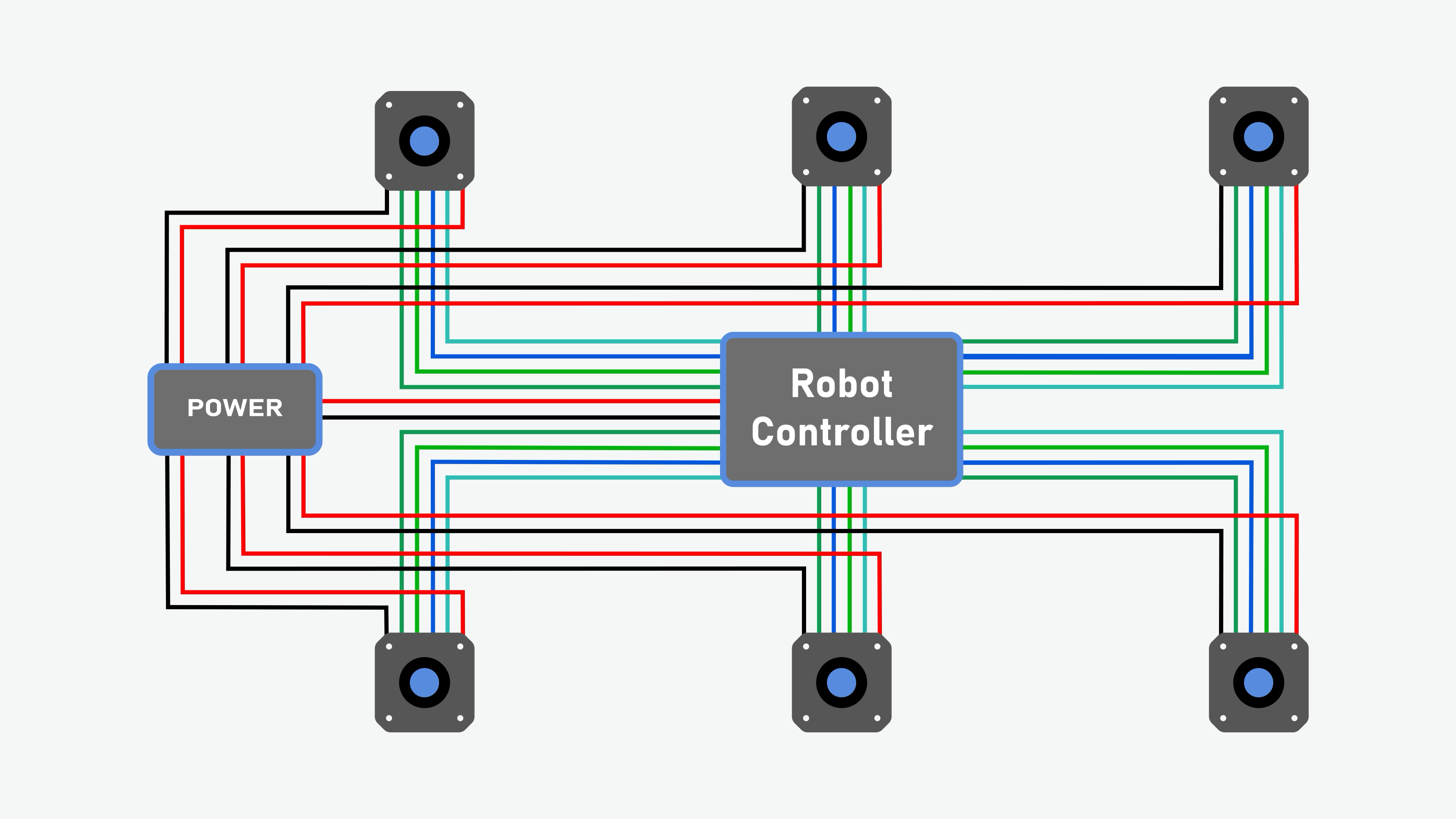
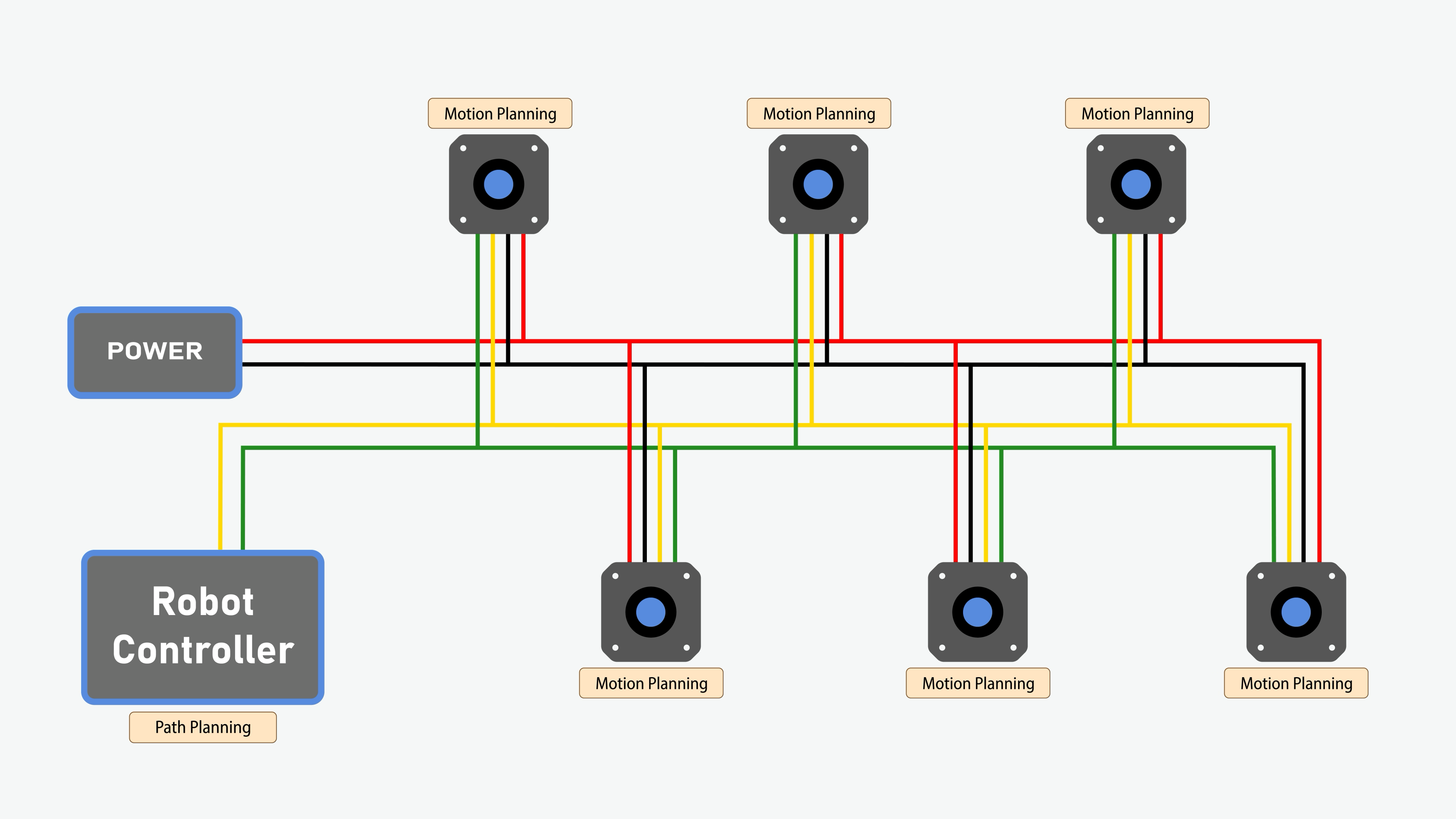
Why run 38 wires when 4 will do? We switched to a CAN bus. Instead of a private road to every house, every house sits on one shared street. Each joint gets its own driver board, and all of them hang off the same 4 wires: 2 for CAN and 2 for power. Now only 2 wires come out of the robot controller, and 2 come out of the power supply. Going from 38 to 4 was the single best decision in the whole project.
The V2 rebuild
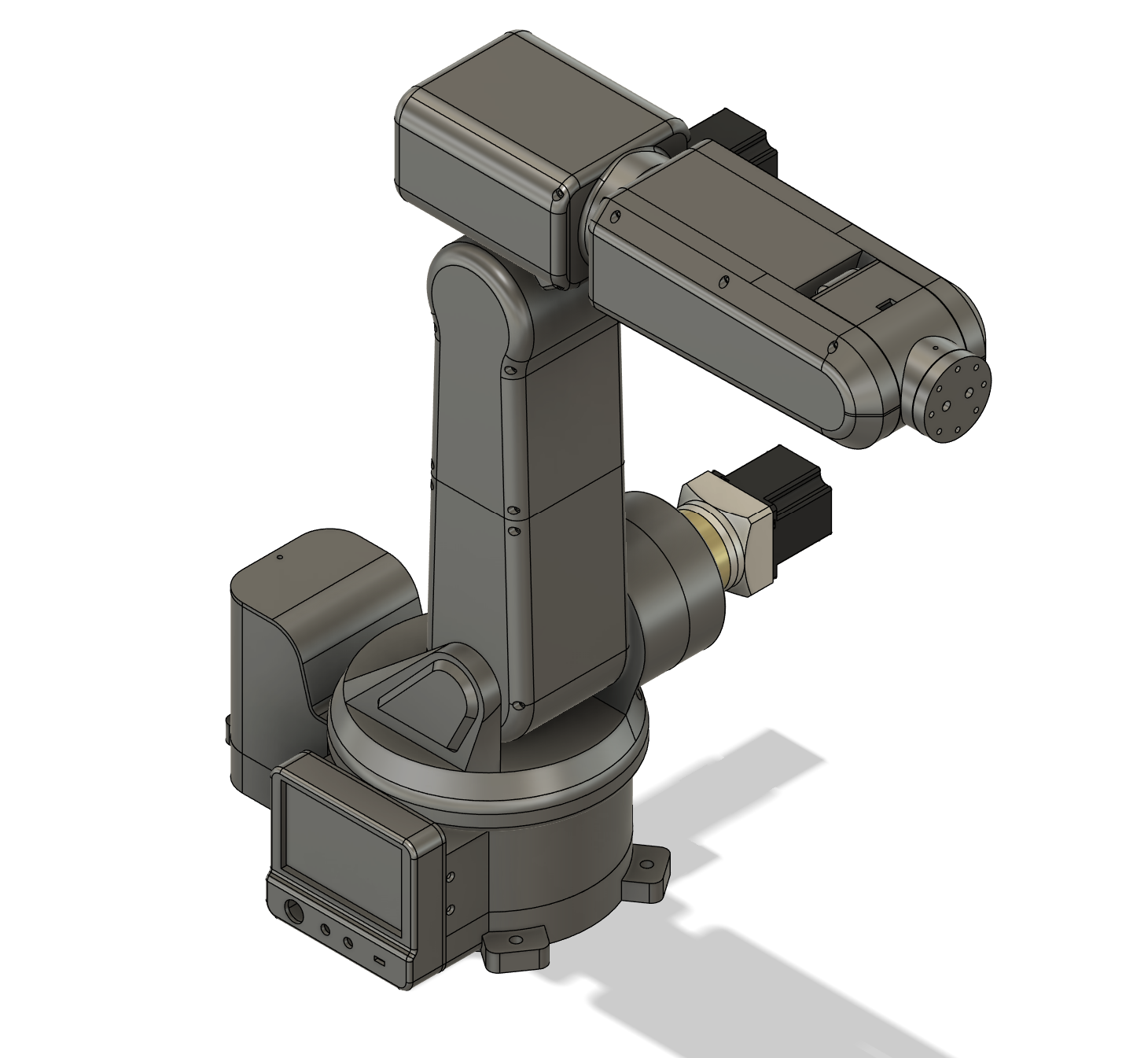
The CAN switch meant redesigning a lot of the arm anyway, so I used the chance to fix the wobble and clean up the rest of the design. The V2 arm is a bit smaller and stiffer than V1:
- A tapered roller bearing now supports the main base shaft. That fixed the wobble, because a tapered roller bearing takes both the side loads and the tipping loads from the arm hanging out over the base.
- Tensioning bearings at J1 and J5, the two joints that still use pulleys.
- Cable channels bored through the joint shafts. The J3 to J4 and J4 to J5 wiring now runs inside the joints, so you can't see it from the outside and it doesn't get pinched.
Homing also got an upgrade. V1 used mechanical limit switches, and they broke. Unplugging the microcontroller once caused erratic motion that snapped the J2 switch clean off. V2 uses inductive proximity sensors instead. They output a voltage when metal gets close, with no contact at all, so there's nothing to break.
Electronics
Steve designed all of this, so I'll keep it high level. There are seven boards in total:
- One main controller: a custom PCB built around an STM32H7. It has a hardware floating-point unit, which matters because the kinematics are all floating-point math, and it has a display controller for a touchscreen we plan to add.
- Six joint drivers: nearly identical boards with an STM32G4 and a Trinamic stepper driver, one bolted to each motor. The NEMA 17 and NEMA 23 boards differ only in the power stage.
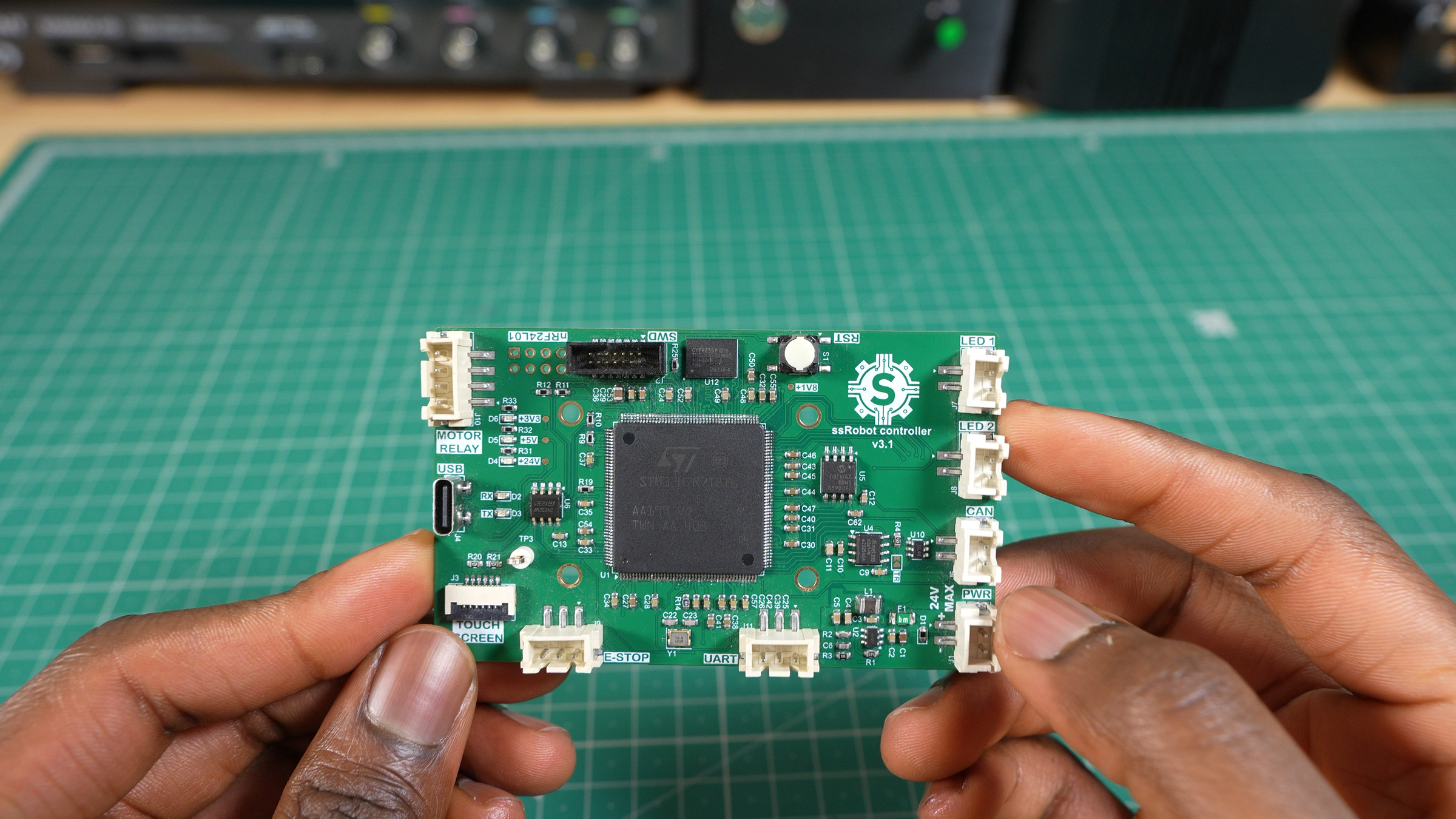
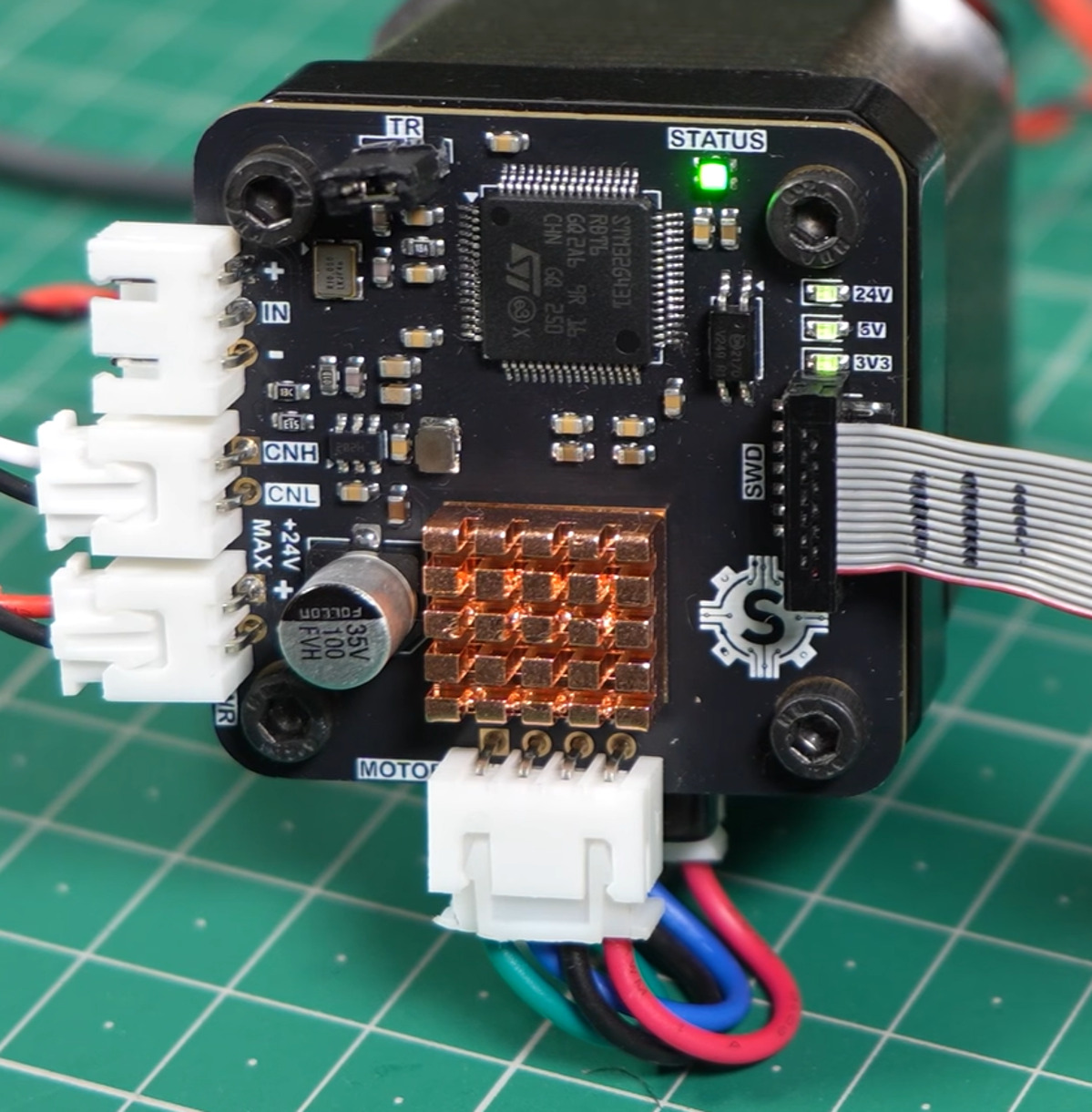
The bigger change is where the work happens. In V1, one microcontroller planned the path and generated every step pulse for all six motors. Now the main controller only sends high-level targets over CAN, and each joint's own microcontroller generates its own step pulses. That's a distributed control system: the processing load is spread across seven boards instead of piled onto one.
We could have bought off-the-shelf CAN servo drivers. But then we wouldn't own the algorithms, and learning those was the whole point.
Fabrication
All of the structural parts are 3D printed. The broken J3 shaft taught me to look hard at infill on anything that carries load.
Inverse Kinematics
Going from joint angles to the tool position (forward kinematics) is easy. You just chain six transforms together. Going the other way is the hard part: you know where you want the tool and which way it should point, and you need the six joint angles that get it there. For a general six-axis arm there's no clean formula for that.
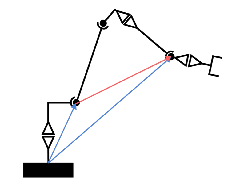
Our arm has one because of the spherical wrist. The last three joint axes all cross at a single point, called the wrist center. Since rotating about an axis can't move a point that sits on that axis, no amount of wrist rotation can move the wrist center. So the problem splits in two:
- J1, J2, and J3 set where the wrist center is.
- J4, J5, and J6 set which way the tool points.
To find the wrist center, you start at the tool tip and back up along the direction the tool is pointing:
Here \(\mathbf{p}_{\text{tool}}\) is where we want the tool tip, \(\mathbf{a}\) is the direction the tool points, and \(d_6\) is the distance from the wrist center to the tool tip (56.5 mm on our arm). Once you have the wrist center, J1 is just the angle of that point seen from above. J2 and J3 come from a single triangle formed by the shoulder, the elbow, and the wrist center, which you solve with the law of cosines. With the first three angles known, the leftover rotation gives the three wrist angles.
To get the wrist angles, we split the tool's rotation into two parts: what the arm does and what the wrist does, so \({}^{0}R_{6} = {}^{0}R_{3}\,{}^{3}R_{6}\). Once \(\theta_1\) to \(\theta_3\) are solved, we know the arm's part (\({}^{0}R_{3}\)), so we undo it to get the rotation the wrist still has to make: \({}^{3}R_{6} = \left({}^{0}R_{3}\right)^{\mathsf T}\,{}^{0}R_{6}\).
Here's the neat part. J4 rolls, J5 bends, and J6 rolls again, so \({}^{3}R_{6}\) always has the same form as a set of ZYZ Euler angles, and its last row and column are simple: the bottom-right entry is \(\cos\theta_5\), the last column is \([\cos\theta_4\sin\theta_5,\; \sin\theta_4\sin\theta_5,\; \cos\theta_5]\), and the bottom row is \([-\sin\theta_5\cos\theta_6,\; \sin\theta_5\sin\theta_6,\; \cos\theta_5]\). Writing \(r_{23}\) for the entry in row 2, column 3, that gives:
Dividing the other entries cancels out the \(\sin\theta_5\). In plain terms, \(\theta_5\) is the angle between the forearm and the tool, \(\theta_4\) rolls the forearm so the bend goes the right way, and \(\theta_6\) spins the tool into place. If \(\theta_5\) is zero, the tool lines up with the forearm and J4 and J6 spin about the same axis, so only their sum matters. In that case the firmware sets \(\theta_4\) to zero and solves for \(\theta_6\) on its own.
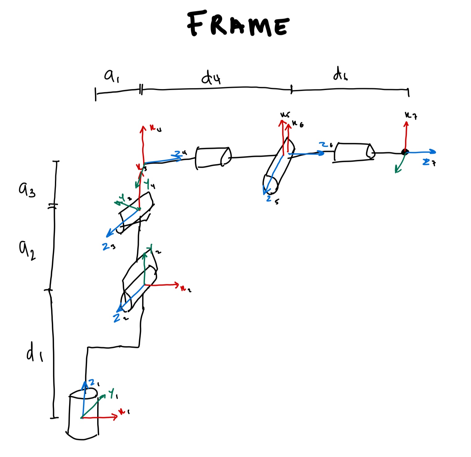
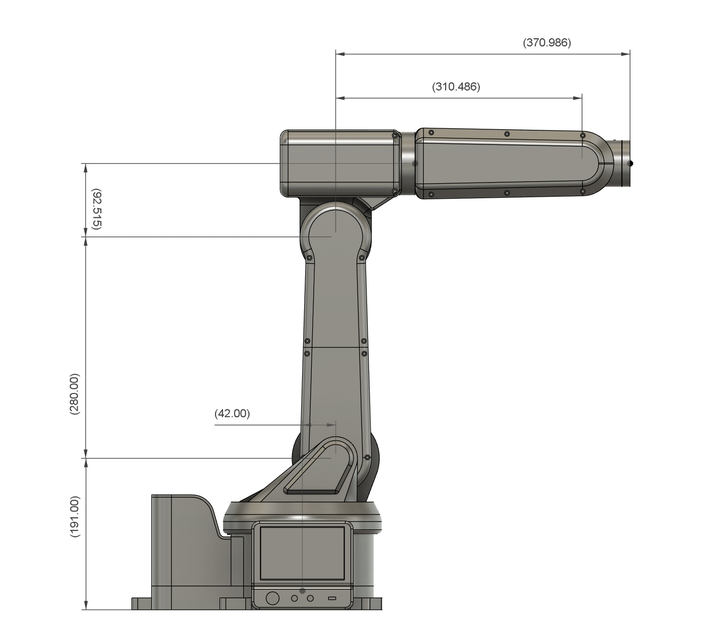
The DH parameters of our arm are \(a_1 = 42\), \(a_2 = 280\), \(a_3 = 92.5\), \(d_1 = 191\), \(d_4 = 310.5\), and \(d_6 = 56.5\) (all in mm).
Path Planning
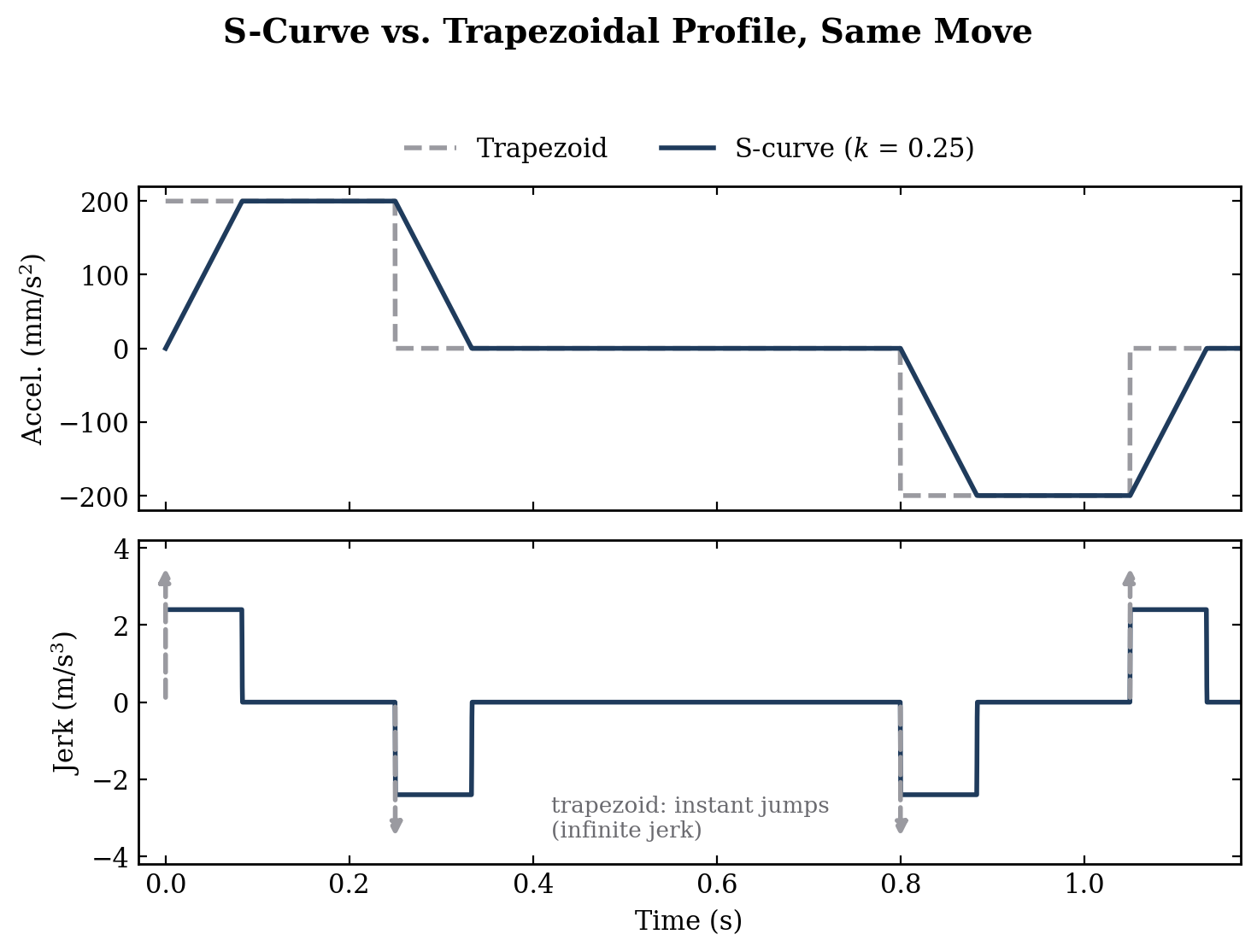
IK tells you where the joints need to be. It says nothing about how to get there. If you just jump straight to the target position, you're asking for infinite acceleration, and on our arm that meant skipped steps, ringing, and a lot of stress on printed parts.
So the planner shapes the speed along every move. The classic way is a trapezoidal profile: ramp the speed up at a fixed acceleration, cruise, ramp down. The problem is the corners. A trapezoidal profile switches the acceleration on and off instantly, and that sudden change (called jerk) is what shakes the arm, so the motion isn't really smooth.
We use an S-curve instead. It has seven phases: ease into the acceleration, hold it, ease out of it, cruise, then the same three in reverse to stop. A single number, \(k\), sets what fraction of each ramp is spent easing in, and the same fraction is spent easing out. \(k = 0\) gives you a plain trapezoid, and our default is \(k = 0.25\).
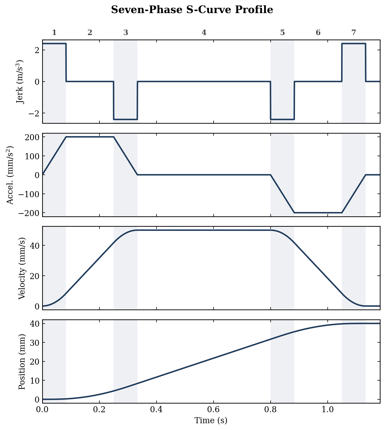
Because you never hold the peak acceleration for the whole ramp, the average acceleration is lower than the peak:
\(a\) is the peak acceleration and \(k\) is the easing fraction. With our defaults (\(a = 200\ \text{mm/s}^2\), \(k = 0.25\)), the arm averages 150 mm/s² during a ramp. The planner has to use this average, not the peak, when it works out how long a move takes and how much distance it needs to slow down.
There's one case where the S-curve is a bad idea. The planner updates 100 times a second, and if an easing phase would be shorter than 20 ms (two updates), the firmware can't actually draw the smooth part. It would just come out as a single jump in speed anyway. So in that case the planner falls back to a trapezoid on purpose.
The planner also looks ahead at the moves waiting in the queue, so it doesn't have to come to a full stop at every corner of a multi-segment path. The default cruise speed is 50 mm/s.
Testing
The video below is the arm running coordinated pick and place with the force-controlled gripper: it picks up a cube and a grape and moves them using straight-line Cartesian moves.
| Goal | Target | Result |
|---|---|---|
| Cost | under $1,000 | $700 |
| Motion | coordinated Cartesian paths | working, see the demo |
Specs
- Total cost: $700
- Degrees of freedom: 6, with a spherical wrist
- Default speed: 50 mm/s cruise, 200 mm/s² peak acceleration
- Motors: NEMA 23 on J2 and J3, NEMA 17 on J1, small integrated-gearbox steppers on J4 to J6
- Electronics: STM32H7 main controller, six STM32G4 joint drivers with Trinamic stepper drivers, CAN bus
- Wires through the arm: 4 (down from 38)
Conclusion
We set out to build a six-axis arm for under $1,000, and the finished arm cost about $700. It follows straight-line Cartesian paths, and with the force-controlled gripper on the end, it can pick up and place a cube and a grape.
Getting there took a full rebuild. The elbow went from a belt that couldn't hold the arm up to a motor mounted right at the joint. The wiring went from 38 wires running through the arm to 4 on a shared CAN bus, with a driver board on every joint. A tapered roller bearing fixed the wobbly base, and contactless proximity sensors replaced the mechanical limit switches.
What's next
Things to fix:
- Close the loop. The magnetic encoders are already on every driver board. Using them would let the arm catch and correct skipped steps instead of trusting the steppers blindly.
- Orientation along paths. Right now a straight-line move holds the tool's starting orientation the whole way. Smoothly blending orientation along the path is the next big piece of firmware.
Things to add:
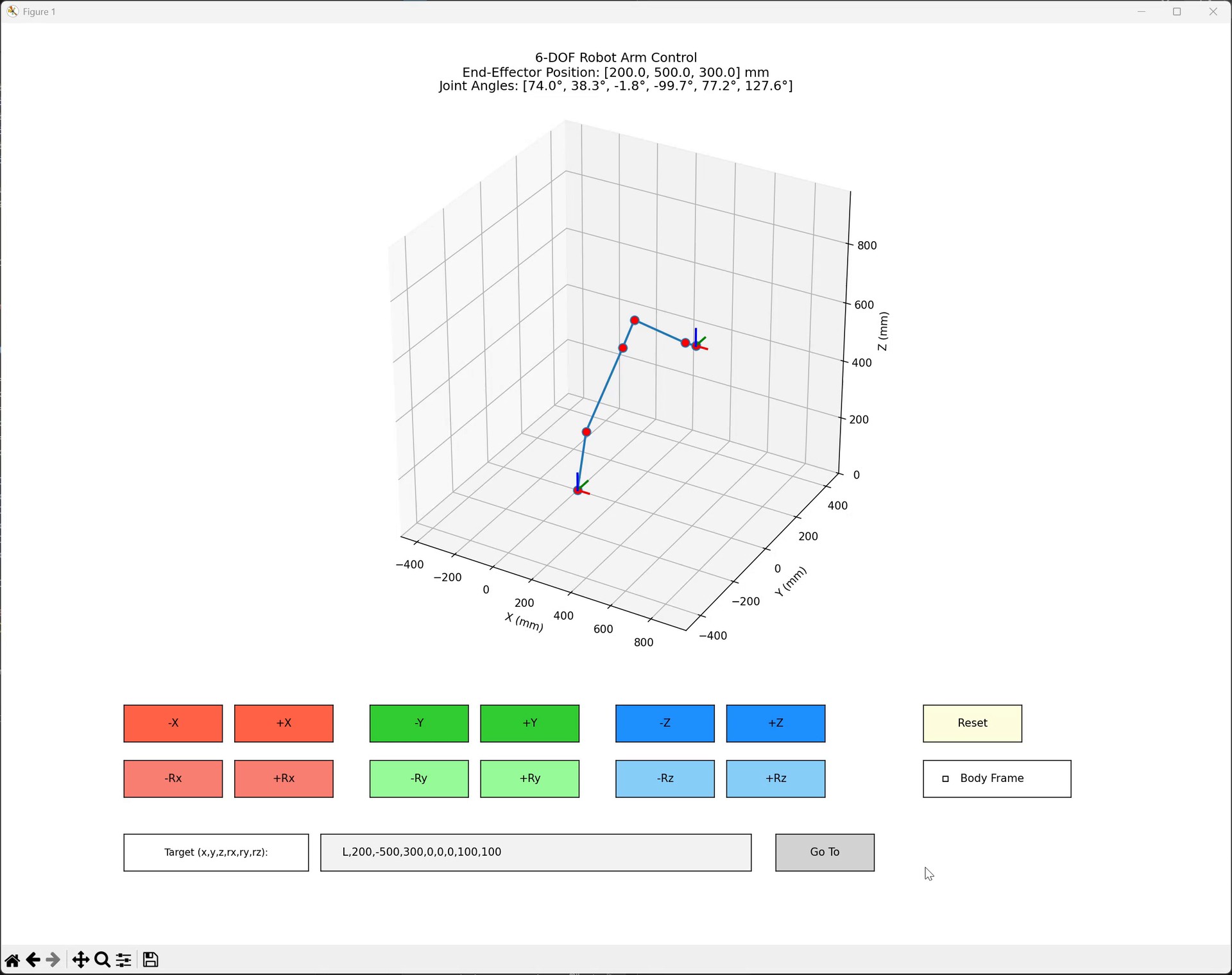
- A touchscreen interface. The display controller is already on the main board.
- Better arc support in the planner.
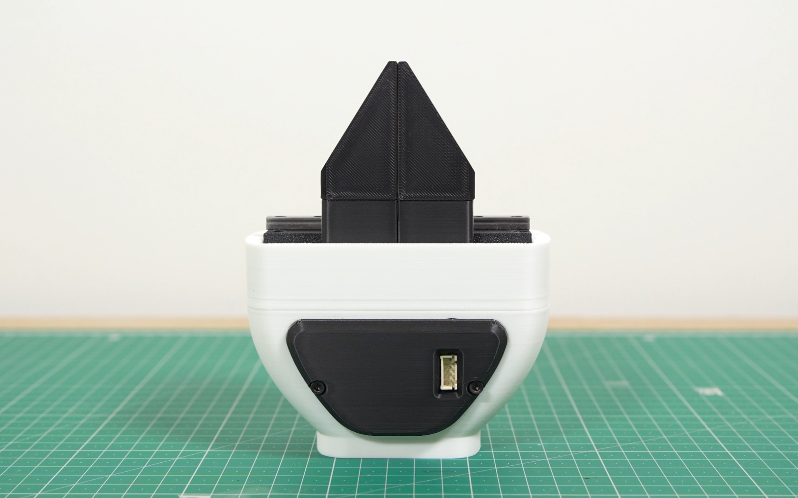
The end of the arm also got its own project: a force-controlled gripper that can pick up a potato chip without crushing it, for under $40.
Thanks for reading!