3D Printer Cooling Upgrade
A dual 5015 blower fan duct, tuned with CFD, for printing at 250 mm/s
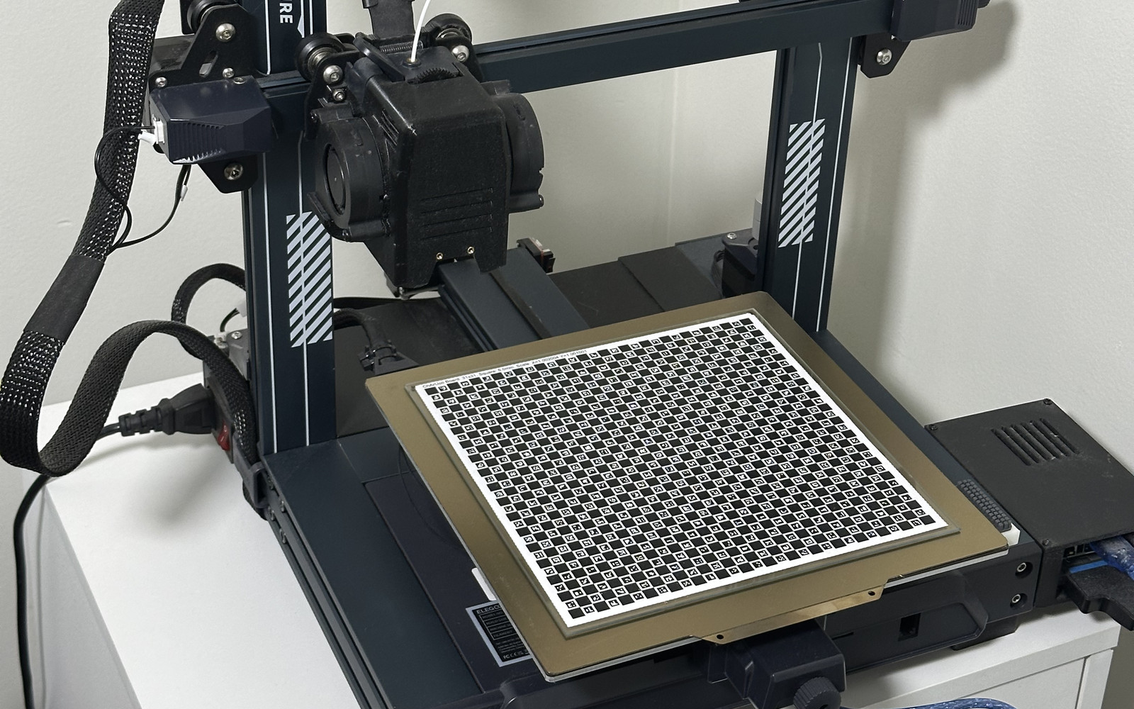
My 3D printer, an Elegoo Neptune 3 Pro, was slower than I wanted, so I switched it to Klipper firmware to get more speed out of it. That fixed the motion side, but it created a new problem: the stock part cooling fans couldn't keep up. So I designed a new cooling duct with two 5015 blower fans, used CFD to work out where the air should go, and ended up printing good parts at up to 250 mm/s, compared to about 100 mm/s with the stock fan.
Why Cooling Limits Speed
When the printer lays down a line of plastic, it comes out of the nozzle soft. It has to cool and harden quickly, or the next layer gets put down on top of something that's still soft. At low speeds there's plenty of time for that. Speed the printer up, and each layer gets less time to cool before the next one lands on it. Without enough airflow, overhangs start to droop, corners curl up, and small details turn into blobs.
So past a certain point, a faster motion system doesn't help unless the cooling can keep up. That point was about 100 mm/s with the stock fan.
Goals
- Print at much higher speeds without losing quality
- Put as much air as possible right under the nozzle, where the plastic is coming out
- Fit the existing toolhead, with parts I can print myself
Design
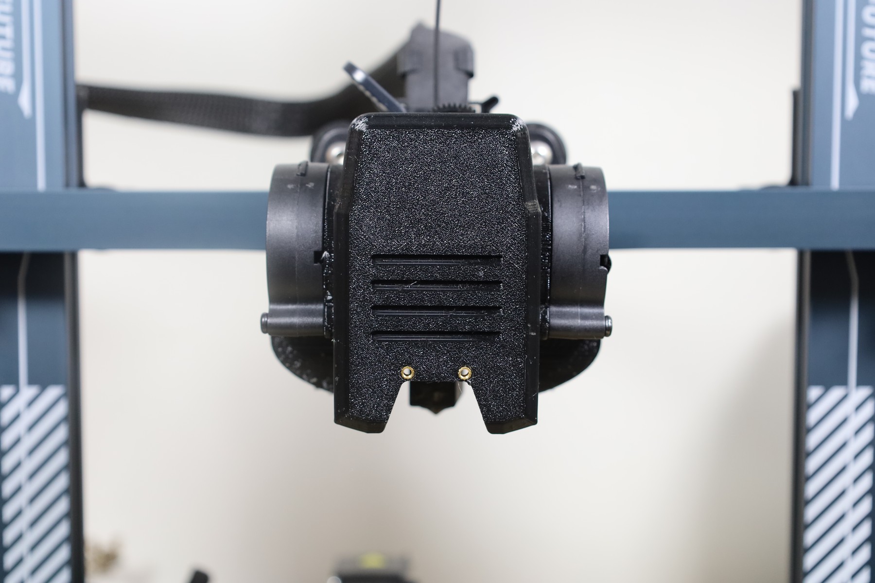
I designed the duct in Fusion 360 around two 5015 blower fans. A 5015 is a 50 × 15 mm radial blower, the go-to fan for part cooling. Blowers push air at a higher pressure than regular axial fans, so they hold up much better when you force their air through a narrow duct. Two of them together move a lot more air than the two smaller blowers in the stock shroud.
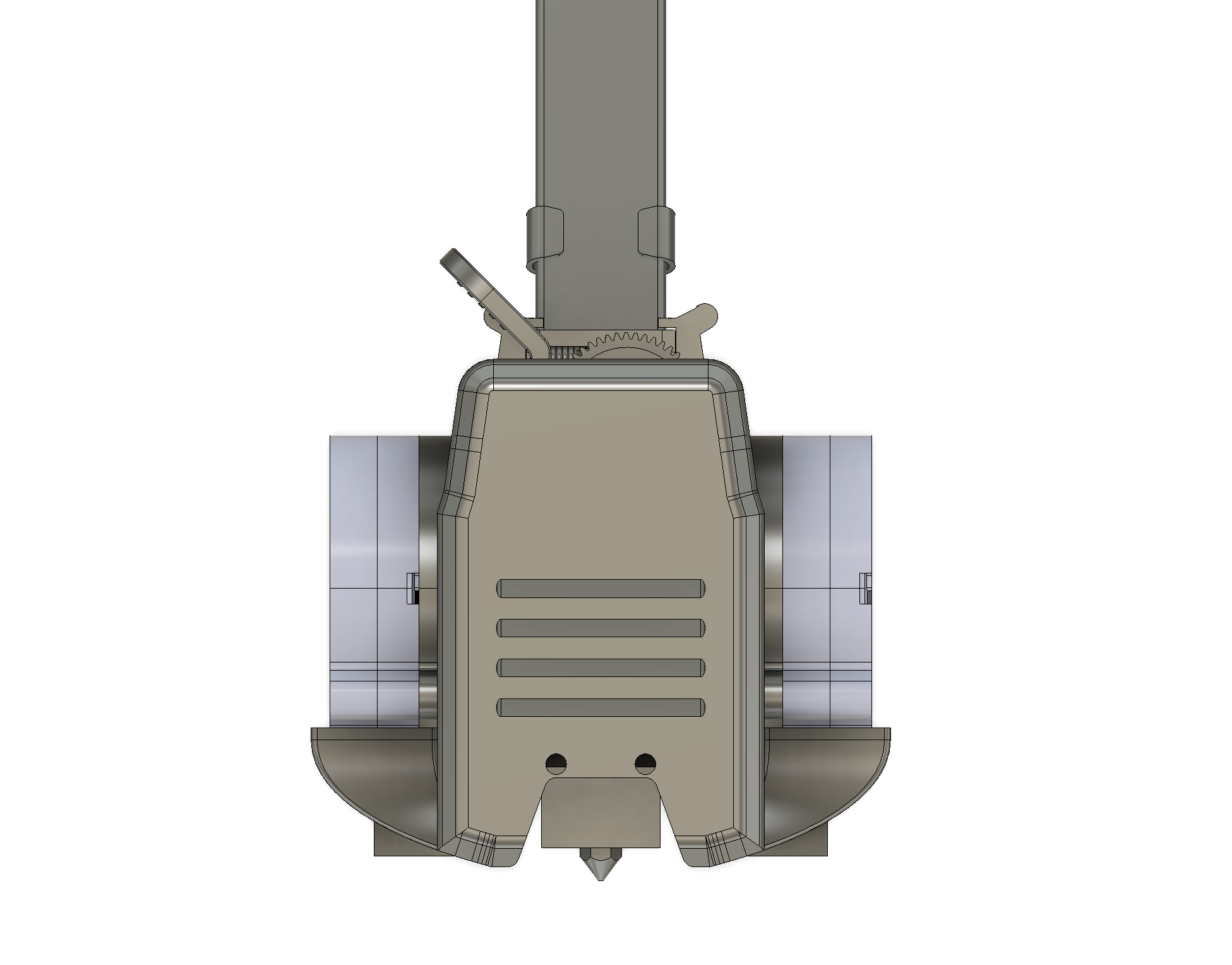
The parts are printed in PETG. It holds up to heat much better than PLA, which matters this close to the hotend, where a PLA duct could soften and sag.
CFD Analysis
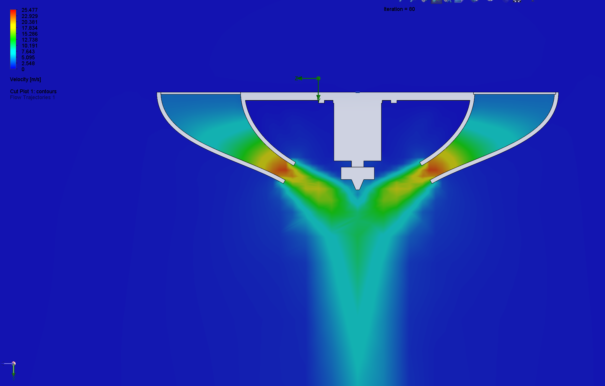
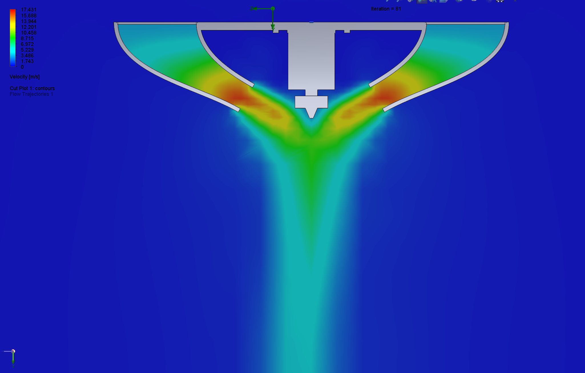
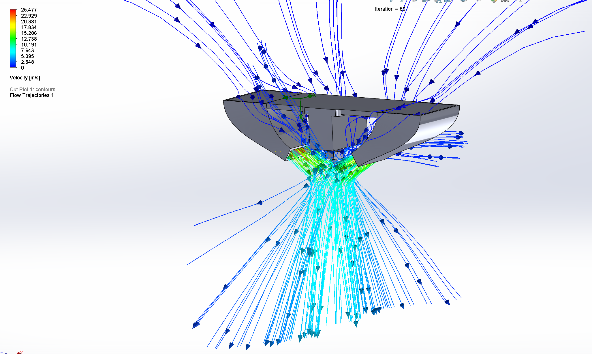
Getting a lot of air out of the fans is the easy part. Getting it to land in the right spot is harder. A duct with the wrong shape can lose most of its airflow to turbulence, or aim it at the nozzle instead of the plastic coming out of it, which just cools the hotend down.
So I brought the duct into SolidWorks Flow Simulation and ran several versions of it, looking for the design that sent the most air directly under the nozzle.
Testing
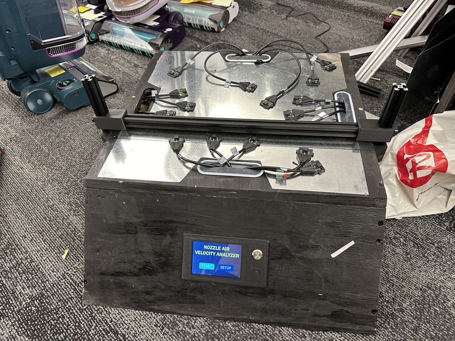
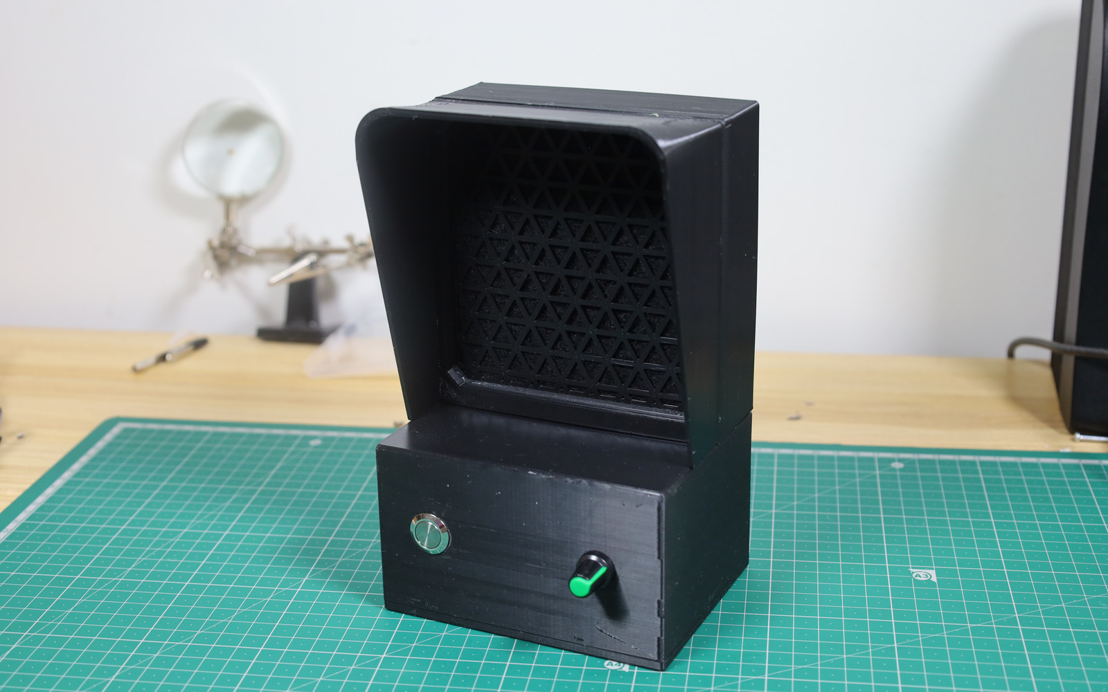
To compare the new duct with the stock one, I did a water displacement test. Both fans ran at 100% speed.
The new duct moves a lot more air than the stock one. More importantly, it holds up in real prints: I can now print good-quality parts at up to 250 mm/s, where the stock design topped out at about 100 mm/s. The trade-off is that the new fans are noticeably louder.
Conclusion
Upgrading to Klipper made the printer faster, but the cooling was what actually let me use that speed. A pair of 5015 blowers and a duct tuned in CFD took the printer from about 100 mm/s to 250 mm/s, at the cost of some noise.
Thanks for reading!